
I’ve been trying to solve an automotive electronics problem for several weeks now, but everyone I’ve spoke to can’t seem to come up with a solution.
In brief, I’m trying to add a relay in-line with the horn switch in my car, such that I can close my own circuit when the horn is pressed, without affecting the existing horn circuit in the car.
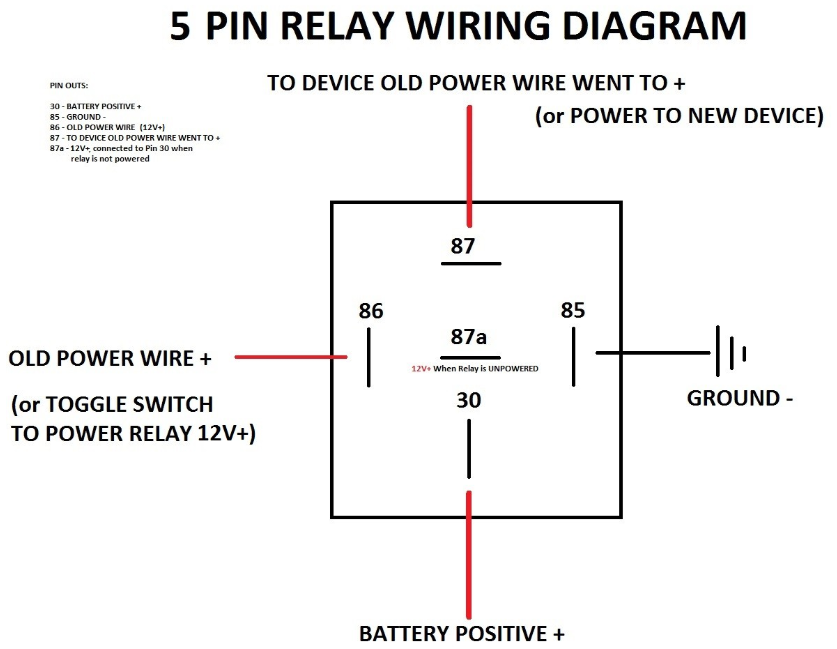
I had some JD1912 12V relays left over from a previous install, so I tried to use those. (Relevant image: Diagram)
First, I placed connected the trigger wire (pin 86) to the the wire coming into the horn switch, and the ground (pin 85). The relay triggered when the horn button was pressed as expected, but this also caused the actual car horn to sound continuously. Presumably doing this was enough to give the factory horn relay enough current to close.
Next, I tried placing the relay in series with the horn switch by splicing the wiring heading into the horn switch, and connecting the relay (pin 86 and 85) in line. Once again, the relay triggered with the horn switch as expected. However, this time, the actual car horn didn’t sound at all.
The best I can work out is that there’s a resistor in-line with the relay trigger (otherwise connecting it straight to ground would cause a short, right?) However, that resistor is just enough to allow the factory horn relay to trigger when connected to ground.
The way the car is designed, I can’t splice into the wire coming out of the switch to detect when the horn is pressed, since it’s a shared ground with other components.
My question is, is there such a thing as a relay with no resistor? Essentially all I’m looking for is a component that will “detect” current on the horn switch wire, and close a separate circuit. I’m not sure if a relay is even the correct way to go about this. Hopefully you guys can point me in the right direction.
Not sure I understand the problem fully, but you want a circuit to operate when you push the horn button, without affecting the horn operation.
Chances are the relay coil is drawing to much power.
Have you thought about adding a transistor to your circuit? It would draw very little current from the horn circuit but should allow you to drive something else. - such as your relay. It would of course require you to do some electronics.
I’ve honestly never worked with transitors. Basically all of my experience is with pre-made 12V electronics. The appeal of the relay method to me was that it felt fairly non-invasive, since my add-in circuit is essentially isolated from the car with the relay (for example, I can trigger the relay with 12V, and switch a 5V circuit without any issue). Would the same be true with a transistor?
Car horns are usually ground switched.
There’s no resistor in a standard 12v relay (other than the coil itself).
This should work with no issues, provided your car has a typical horn circuit.
Check a wiring diagram for the car. Cars used to run the horn circuit through the horn switch on the wheel directly, no relays or anything else - the power for the horn went through the horn switch (well , the ground side anyway, which still has to support the horn current load).
Automotive relays generally take very little current to operate (like 0.5 amp) - it’s kind of their function to switch a high-load circuit using a low-current circuit.
I can’t splice into the wire coming out of the switch to detect when the horn is pressed, since it’s a shared ground with other components.
This doesn’t add up. If it’s a shared ground that’s switched, then other things wouldn’t work if the horn switch wasn’t engaged.
This is a typical horn wiring.
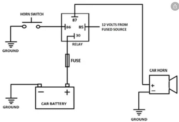
You’d want to wire your relay the same as the horn relay (ground switched, tapped into the wire between the horn switch and relay), or use #87 as your trigger into your relay’s #30 (wiring your relay as positive switched, typical config), or even more easily, just wire your actual device to #87, as horn circuits generally have moderate current capability (the wires are often 14 gauge).
Essentially all I’m looking for is a component that will “detect” current on the horn switch wire, and close a separate circuit.
I think you’re describing a transistor
There are coils which can detect current through induction, so you can trigger on press without altering the resistance of the circuit
You may be able to use a optocoupler to sense the horn then use that to trigger the relay. What are you trying to accomplish? Are you making like sensor to know when your car alarm has triggered?
Right now I’m trying to hook up a custom dashcam that can show an overlay when the horn is pressed. It works via GPIO, and essentially just checks to see if a specific pin is connected to the ground pin. I figured putting a relay between those two pins with a small resistor for safety would be the least invasive way to do that.
Why not just add a new switch or button to the car? Like a button for your left foot to hit like old headlight high beams were.
The idea is that the dashcam can show when the driver presses the horn in a car accident without the driver needing to do anything different. Anyone can drive the car without any specific knowledge, and the camera will just work in the background.
If you’ve even seen police dashcam video with the text overlays at the bottom reading “[HORN] [SIREN] [LIGHTS] [BRAKE]”, this is essentially a custom implementation of that for more general use.
You need to find a schematic for your car’s electronics in order to get a proper solution for what you’re trying to do. I would be particularly cautious about connecting a relay coil to some unknown wiring. The back e.m.f. from a discharging relay coil could easily fry a microcontroller if it happens to be connected to one.
I’m confident the wire I’ve tapped into is the horn, since I’ve previously used it to install a horn override as part of a PA system. That being said, I hadn’t considered that I might be connecting to a computer rather than something more analog. When I press the horn, I can faintly hear a relay clicking in the engine bay, so I’m hoping it’s just a simple relay.
Automotive relays have built in back emf protection diodes.
Horn switches switch to ground. Power for your original horn relay is supplied from a fused battery source, passes through the horn relay, and when you press the horn button the button completes the circuit to earth, triggering the relay.
So, you need to wire your relay coil like this -
12 volts from a fused battery source to:
Your relay coil, to:
The horn switch, which then switches to:
Ground.
Just like how your current horn relay works.
This also works for older cars that do not have the really. They supply power to the horn, and then a single wire runs from the horn back to the horn button, which then completes the circuit to ground when pressed.
Relays operate by flowing current through a coil. The coil generates a magnetic field, which attracts a ferromagnetic plate that then closes contacts. Without current flow, no relay can operate.
This coil has a standard resistance/impedance based off the length of wire coiled, ans is engineered depending on the size of relay, designed operational voltage, etc. This cannot be modified.With a series of solid state op amps, one could turn a “no current/infinite resistance” signal into a relay switching effect, but it would require some other outside power source to run the relays or mosfet switching. Seems complicated. Maybe look for a “solid state relay” or “digital relay”, I’ve not ever used one though.
I know you weren’t operating a car horn directly through a relay coil either, so there must definitely be some other relay or more likely a BCM computer with a MOSFET on board.What year/model of car? Is there any chance you can locate a oem wiring diagram to understand better how the horn system works? In older cars, the horn is a ground-switched circuit, where the horn unit is always hot +12v and then it is directly connected to ground through the steering column when the contacts on the horn pad are pressed together. No intermediate relay. On a system like this I would connect the relay effectively “in parallel” with the horn, with one side of the coil on +12v hot, and the other on the non-grounded, switched side of the horn pad. This way the horn and coil sit at the same potential and no current will flow anywhere except the horn pad ground circuit when pressed.
I cannot guarantee any newer car uses a system remotely like this though, especially through a computer so YMMV.
And realistically you could in a pinch pull coil power from the horn itself. Just connect a wire to either side of the horn so your relay coil is in parallel, one side switched and the other side always hot/ground. This may/may not be safe though as the horn circuit will likely be in a relatively large fuse and it’ll be impractical to relocate the relay or run an additional 14 feet of small gauge sense wires from the cabin to the front of the car.
This coil has a standard resistance/impedance
I see. I was under the impression that there’s a seperate resistor to avoid shorts when you connect from the trigger to ground.
What year/model of car?
It’s a 2014 Nissan Altima. I’ve spent quite a bit of time trying to find wiring diagrams, but I haven’t gotten very far. I got to the point I’m at now by following some old forum posts and confirming with a multimeter. What you described sounds accurate: the horn wire under the steering column seems to always be at 12v. Pressing the horn seems to send it to ~0V, so I assume it’s just jumping to the shared ground wire. I will say that when I disconnect to horn at the front of the car (to silence it), I can hear a relay in the engine bay clicking when I press the horn. I figure that implies it’s a physical relay, rather than a computer somewhere.
And realistically you could in a pinch pull coil power from the horn itself
This is something I’ve considered doing. The circuit I’m adding with the relay is extremely low current, so I don’t think it would be too tricky to run wires from a relay connected right next to the horn to the cabin. I can just ground the relay to the frame of the car right near the horn such that there’s minimal chance of creating a short on the high-amp horn circuit.
It’s a 2014 Nissan Altima. I’ve spent quite a bit of time trying to find wiring diagrams, but I haven’t gotten very far.
Can you not just stick a diode in line with your trigger wire so you don’t get feedback from the relay?
It seems like the horn wire is normally at 12V, and pressing the horn brings it down to about 0V. I figure the horn switch it just shorting that wire to ground, which in turn triggers the factory horn relay. Would a dioide in like with my trigger relay stop the add-in relay from connecting the factory horn wire to ground?
Would a dioide in like with my trigger relay stop the add-in relay from connecting the factory horn wire to ground?
Yeah. Put the stripe end towards the horn wire you are tapping into.
Edit: I just reread your post. If 86 is connected to your car’s horn wire, 85 needs to be connected to 12v, not ground. That’s probably the issue you’re running into (but I would still run a diode for isolation).
85 needs to be connected to 12v, not ground.
I think you may have just solved my problem. When I’ve used relays in the past, pin 85 was connected to ground, since I wanted the relay to close when the trigger went high. I’m not sure why it never occurred to me that I’m essentially trying to do the opposite thing here, since the horn is triggered when the trigger wire is connected to ground.
I’ve never worked with individual diodes, so I’m not sure about the correct terminology, but which way would I want the diode to “face”? Do I want it to allow current to run from the 12V source, through the added relay, to the horn switch wire, or the other way around?
Additionally, would I need to add an in-line resistor? It makes me a little nervous connecting the horn switch to 12V, given that I doubt it’s designed to carry a significant amount of current.
You need to put in a double pole relay. Disconnect the horn from the original switch entirely and connect it to one of the relay poles, connect your circuit to the other.
Or just use a single relay and put the horn and your other load in parallel as long as they both run on 12V.
The horn button gets connected to the coil of the relay.
Relays don’t have resistors necessarily in their coils, but the coil is designed to draw a certain amount of current at a certain voltage. In essence it is a resistor. If it were to pass the full current required to drive a car horn through the coil, it would catch fire.


